|
Battery
Management
System Processor - discontinued 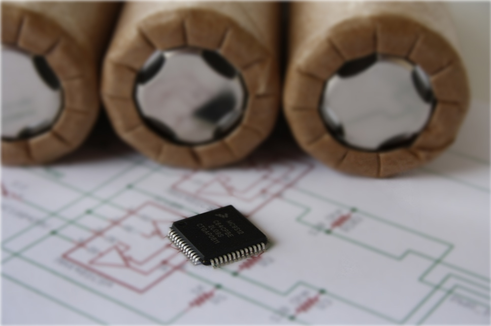
|


| |
|
|
||
|
|
|||
| |
|
|
|
|
|
|
|
|||
|
|
|
|||
|
|
|
|||
|
|
|
|||
|
|
|
|||
| |
|
|||
|
NOTE: This product is no longer available. I have left the information on this page for information only and assume no responsibility for its use. Overview: Cell management inside a modern lithium ion battery pack is critical in maintaining and prolonging the health of the pack. This cannot be done without having constant, up to date information being gathered from the individual cells that make up the pack. To provide a generic BMS (Battery Management System) that can provide all of the features that every different application requires is a difficult task, and, to further complicate things, each application requires different physical characteristics including cell size, shape and mounting. Creating a BMS that can provide pack monitoring and management for an electric automobile would be very different than for an unmanned vehicle or for a stationary emergency back up power supply. To create a complete BMS from scratch for each application is also very expensive and time consuming and for this reason, Zanthic Technologies has created the Battery Management System Processor for your OEM, installer or custom design requirements.What is it? Although it may be impossible to make a BMS system that can be applied to all applications, it is possible to start with a common system and adapt the physical hardware to fit the application while adding or removing software features as needed. What Zanthic is providing is a starting point to your OEM development and a method of manufacturing all of the software features into your system without the initial development costs.What we provide is the following:
What is the cost to manufacture? You are in total control of your hardware design and the associated manufacturing costs and the only component you purchase from us is the the microcontroller but we do highly recommend that you to purchase a demo package for initial evaluation. The configuration software is free of charge and uses our CAN-4-USB/FX interface for connection to the CAN bus. The microcontroller comes with a built in CAN bootloader that allows you to update the firmware should changes be released in the future. Any future firmware versions for this processor are provided to you without additional cost and may contain improvements and additional features. The firmware update is done directly through the configuration software and the CAN-4-USB/FX interface and is quick and easy to do. The bootloader will always stay resident and even if the download fails, your board will never be rendered unusable. There is no additional licensing costs to you and you are welcome to modify your hardware design and retain ownership of your custom design.What about custom modifications? We are available for custom hardware and software modifications to suit your application and needs. Because all of the hardware libraries already exist it is very time effective for us to create new versions for you.What about ready to install boards? We provide demo boards for evaluation but these are not certified for actual implementation in an end user environment due to individual industry requirements for certification. Demo packages are available with all of the components required, included master and slave board, power supply, cables, LCD and CAN-4-USB/FX interface.See additional links at the bottom of this page. 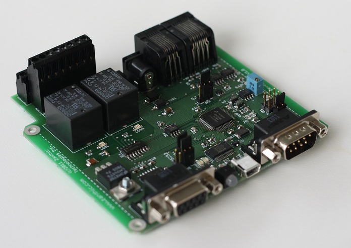 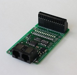 Master and slave demo boards are shown in the above pictures Features:
More information: NOTE: This product is no longer available. I have left the information on this page for information only and assume no responsibility for its use. The original prototype for this system is described on the following page. Please note that some features have been expanded upon and will not be shown or described in the prototype. The prototype refers to the LTC6802-2 device and all firmware has been updated to the 6803-2 device. The 6802-2 is no longer supported.Lithium Ion Battery Management System with Linear 6802 Slaves Cheetah64 with 6803 BMS firmware...Brochure Cheetah64 with 6803 BMS firmware...Datasheet Cheetah64 with 6803 BMS firmware...Demo Board Manual If you would like to ask additional questions, please contact me by email at
|
Zanthic Technologies Inc. Copyright © 2011 Zanthic Technologies Inc. All rights reserved. |