
|
Projects Lithium Ion Battery Management System with Linear 6802 Slaves This page outines my original prototype BMS system.Please feel free to email me at with your comments or questions. |


| |
|
|
||
|
|
|||
| |
|
|
|
|
|
|
|
|||
|
|
|
|||
|
|
|
|||
|
|
|
|||
|
|
|
|||
| |
|
|||
|
Overview: This project is a complete battery management system to monitor lithium ion cells. I use the term lithium ion as a general term to mean any number of specific types and chemistries of cells, including (but not limited to) LiPoly, LiFePO, LiMn etc The system is comprised of a micro-controller Master that can communicate with up to 16 Slave boards. Each slave can monitor 12 series cells. One master can therefore handle 192 series cells and if required, up to 126 masters can exist on the same CAN network. Each slave is fully isolated from the communications bus and therefore the master and is also isolated from every other slave. This means that each group of 12 cells within a slave can be added in series or parallel or whatever combination of the two that is required. The slave circuitry is based on the Linear Technology's LTC6802 cell monitoring IC. This device communicates with the master through an SPI bus. The SPI bus is a high speed, logic level communications method between a micro controller and a slave circuit. Normally, the SPI would be used on a single circuit board within a short distance and is not normally designed for extended wire lengths going off circuit board. Combining this limitation with a battery pack running high current loads would normally be asking for a lot of communication errors. For that reason, I have modified and significantly improved the standard SPI method by converting the external SPI bus to a bi-direction, fully differential drive circuit(s) while still maintaining complete compatibility with the existing 6802 protocol. Please refer to the separate pdf paper here Differential bus communications for the Linear Technology 6802 device The entire system is completely configurable with easy to use configuration software allowing a modular system that can grow from 4 cells to 24,000 cells! Encrypted firmware updates can be downloaded to the master through the CAN bus interface. This system could be used in a number of ways, including
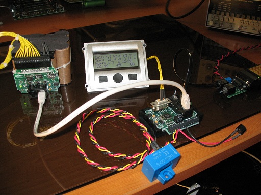
The above
picture shows one of my test setups with a 12 cell E-Moli
pack with a slave board strapped to the front, an off the
shelf
4*20
line RS232 LCD screen with three buttons, a 50 amp current sensor
(blue) and the master controller with a CAN-4-USB/FX interface
partially seen to the right.
Standard Ethernet cabling connects the master to the slave. Each slave has two connectors to allow for easy daisy chaining of slaves together.
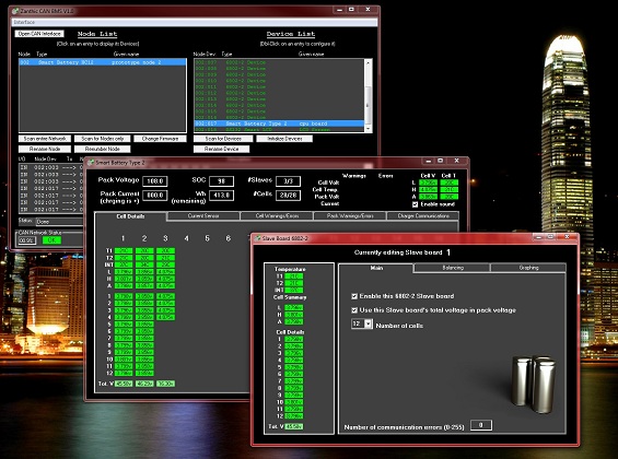
Screen
shot of the configuration software.
Master Controller: - CAN bus running at 500Kbps for communications to configuration software and external devices like CAN enabled chargers- Built in boot loader in micro controller allows for easy upgrading of firmware from encrypted file - Mechanical relay and 3 low side driver outputs (50mA each) fully configurable in function - Analog input for current sensor with configuration capable of handling a wide range of devices - 3 Digital inputs (not currently being used by firmware) - RS232 with power for use with external LCD screen - Differential bus for external SPI communications to slave boards through standard Ethernet cabling - Configurable CAN messages for controlling external charger 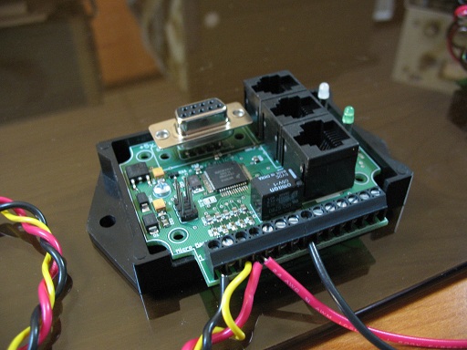 Master
controller
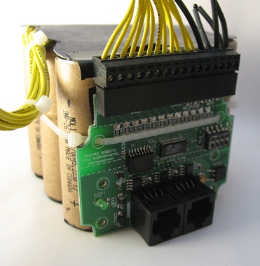
Slave Controller: - Based on Linear 6802 with differential SPI communications- Optically isolated from each other and from communications bus - Power draw of 14mA@12vDC on communications side from master. Power draw of 1.1mA from battery side - Monitor 4 to 12 series cells, 1.5mV resolution with internal or external cell balancing - 2 external temperature sensors and one internal (IC) temperature sensor
This
is the slave board strapped to a 12 pack of E-Moli cells. You
can see the 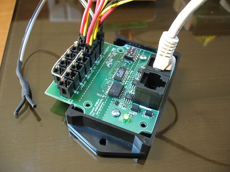 This is a different version
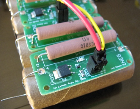
of the slave board to accommodate external balancing circuitry.
The
above picture is a larger current, external balancing board that would
be used on a Firmware: - Configurable pack Ahr rating, current sensor settings, initial SOC start point- Set point alarms for - Low cell voltage warning and error - High cell voltage warning and error - Low cell temperature warning and error - High cell temperature warning and error - Low and high pack voltage warning - High current charge and discharge error - Slaves not responding error Each of the warnings and errors can have an individual trigger point and you can configure which output to activate when triggered. This means you could have one output activate when any single cell reaches a certain voltage and another output activate when the voltage is at a higher point (for example) You can also have an output trigger on any (or all) of the warning or error set points. More information is provided on the configuration screen shots below. - Configurable number of cells connected to each slave, from 4 to 12 - Enable the slave voltage to be used in calculating total pack voltage because in some cases the packs may be in parallel so the total pack voltage would come from only one of the slave - Ability to turn on balancing at a set voltage point, or - Turn on balancing if cell voltage is above the pack average voltage by a configurable amount. This allows balancing to occur at any time the individual cell is too high. - Configurable maximum number of cells to be balancing at any one time. This feature allows the heat generated by either the internal mosfets or the external resistors to be controllable by setting the maximum cells (within one slave) to be balancing at any given point. Of all the possible cells to be in balance mode, the master will choose the highest voltage cells and activate them based on the maximum number in the configuration. - Manual balancing mode where you can create a voltage set point and the cells will turn on balancing until the voltage reaches that point and then turn off automatically. The maximum number of cells balancing at any one point applies to this feature as well. - State Of Charge is determined by measuring current flow in and out of the pack and determine the SOC using the pack's amp hour rating that you configure. Currently no compensation is made for temperature changes or over current conditions in the calculation of SOC |
||
| LCD Screen: - RS232 4*20 line LCD with switch inputs for screen control - Multiple screens from very simple, showing only voltage, current and gas gage to complete cell by cell detail - Two outside buttons scroll through pages, inside button returns to home page. Pages are automatically added as slaves are enabled on the system - Outputs for LED's or alarm buzzers can be set to respond to warning and error conditions - Powered from master controller through RS232 port 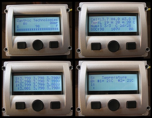 The
above picture shows four different screen shots from simple to more
detailed. Note that there where no slaves plugged in with the
upper left screen shot that shows zero voltage for the pack (oops).
The upper right screen shows low, high and average cell voltages for entire pack and low, high and average temperatures for pack, that there are 3 out of 3 slaves and 28 out of 28 cells communicating and that the state of charge is 98%, the pack voltage is 107 and no current is flowing. The lower screens show the detailed cell voltages and temperatures for slave #01 |
||
| Configuration Software: The configuration software runs on a Windows PC with drivers for 64bit Vista and Win7 available and communicates to the master controller through my CAN-4-USB/FX interface. Note that the DLL for this interface is available so you will be able to write your own Windows software for monitoring the CAN bus data from this system, should you wish. The configuration software consists of three main screens 1) The entire network screen. This shows the different master controllers that exist on the CAN network and when you click on the node entry, it shows the devices that are configurable within that master controller. 2) The main pack configuration screen. This screen shows a summary of all the cells as well as all of the warning and alarm conditions are set here as well as other I/O configuration 3) The individual slave board screen. Each slave can have a unique configuration. 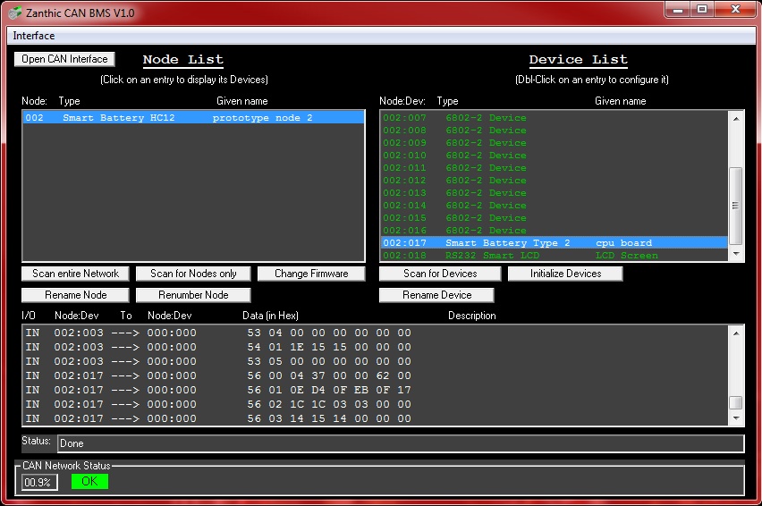 |
||
|
This
is the main screen showing that one master controller exists on the CAN
network and that there are 18 devices within that controller that can
be configured (16 slaves, the pack itself and the LCD screen)
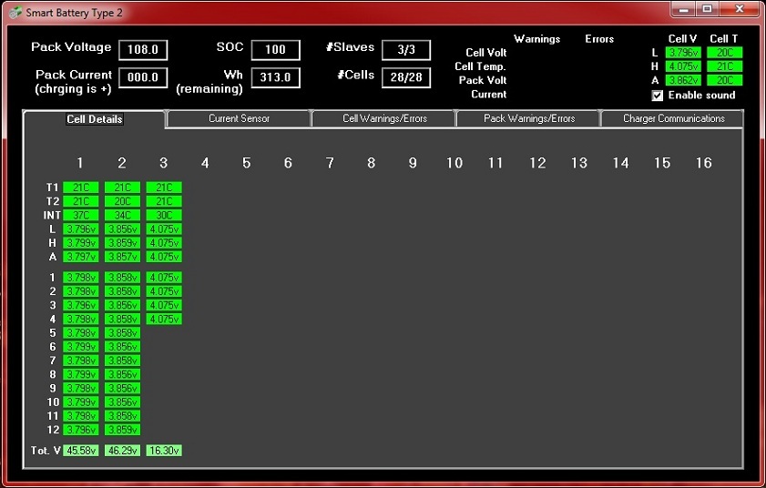 This shows
the main configuration screen for the pack itself with this tab giving
a look at
all the individual cell voltages and temperatures. At the top is all the pertinent pack information 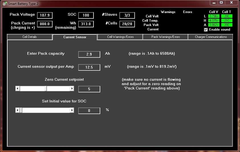 This
tab contains the configuration for the pack capacity which in turn is
used to determine the SOC and watt hours remaining. The
current
sensor can be any sensor that is 5v based with a zero current reading
around 2.5v To allow for an offset from 2.5 volts, the zero
current set point can be adjusted from 1.9 to 3.1v By simply
plugging in the mV setting for a current sensor you can use any range
of sensor, from a few amps to thousands of amps.
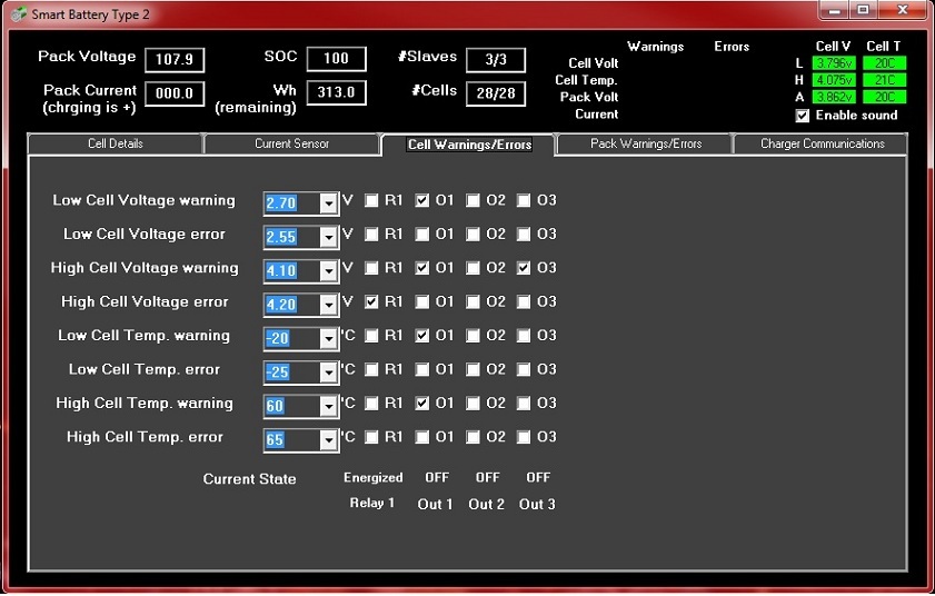 This
tab allows you to set the individual warning and error thresholds for
the individual cells. Note that there is a warning and error
threshold which is really meant as giving you two individual set points
for each. For example, this allows you to trigger a buzzer if
any
cell voltage drops below a certain point and turn off the pack if a
lower threshold is reached. Or, conversely, you could have
your
charger respond to one upper voltage to go from a constant current mode
to a constant voltage mode and then have a higher threshold to end the
overall charge.
Note that for each warning or error, you can choose whether it activates any of the outputs. Also note that the relay is special in that it releases if any of the warnings or errors occur (that have the R1 checked) This ensures that if the relay is used to enable charging (for example) that a power off condition, a micro reset or any of the warnings or errors will release the relay and stop the charging. In the above example, the relay will release if any cell goes to 4.2volts and the Out1 is connected to a buzzer and will activate if any of the 4 conditions apply. The Out3 output will activate if any cell voltage hits 4.1v 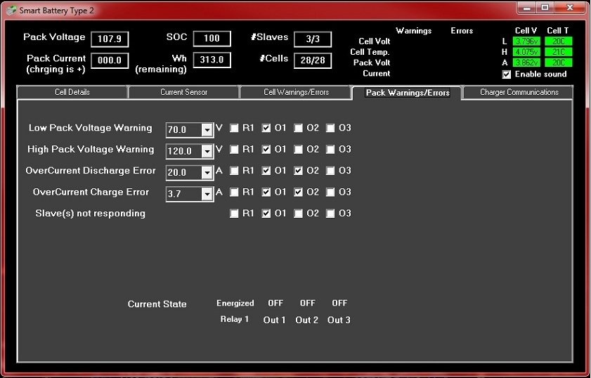 This
screen shows the similar warnings and error thresholds for the pack
itself. In this case, the Out1 output will trigger on any of
these conditions and the Out2 will trigger on an over current
situations.
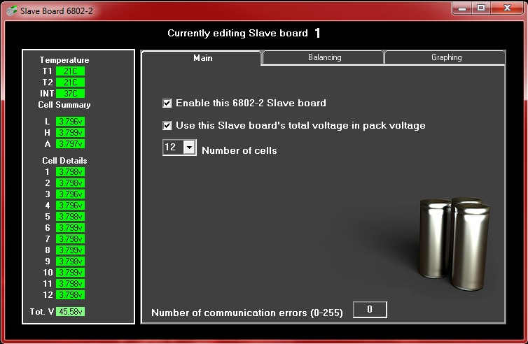 When you choose to configure an individual slave board, you are presented with this screen. From here you can see all of the cell voltages with the low, high and average voltages as well as temperatures. I think the rest of the configuration is self explanatory. Communication errors are monitoring and displayed on this screen to give advanced warning of potential wiring issues. 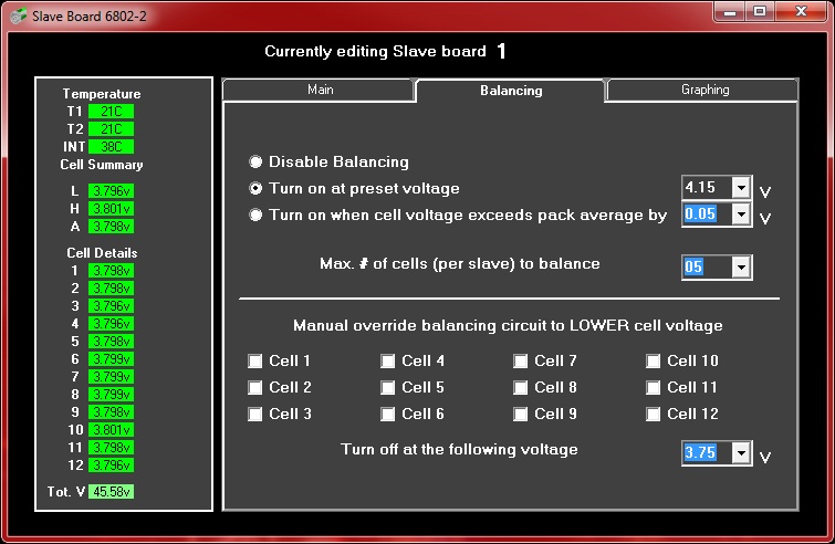 This tab allows you to configure the cell balancing method should you choose to enable it. You can set the balancing to either turn on at a certain threshold (4.15v in the above example) or if the individual cell exceeds the pack average by a set amount (in 50mV increments) You can also set the maximum number of cells to balance at any given time. This can serve a couple of purposes, 1) if you are using the internal 6802 balancing mosfets and you don't want to heat the device excessively or 2) you are using larger external balancing mosfets and resistors and you don't want to heat your pack excessively. The lower portion of the screen allows you to manually lower any cells voltages and have them turn off at a certain threshold, in this case 3.75v 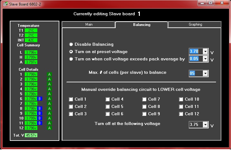 This screen shot shows the balancing set to 3.7 volts and shows that all 12 cells are (A)utomatically in balance mode but only 5 are actually on because we have set the max # of cells to balance at 5. In this case, because the cells are so close in voltage, the balancing will jump around from cell to cell because as the balancing turns on, it will lower the cell voltage slightly which in turn will cause another higher cell to be switched on at the next check. 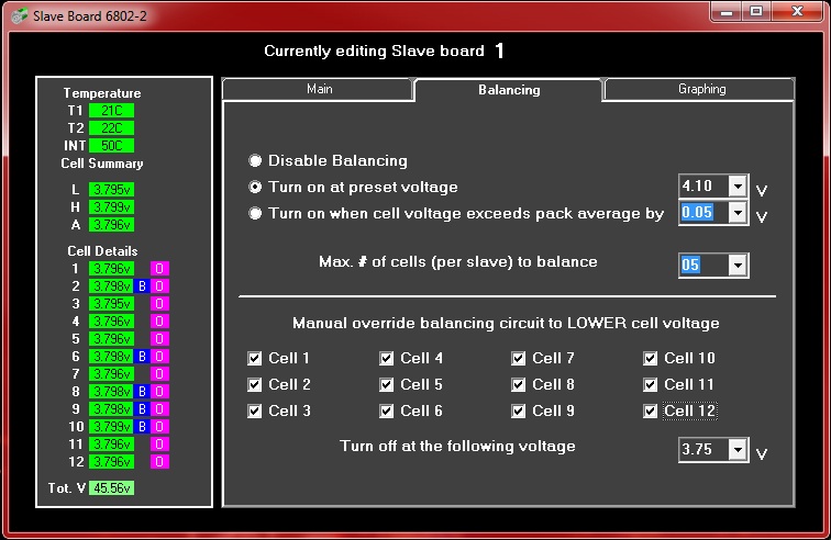 This screen shows the manual (O)verride feature turned on with the same 5 cell limit being enforced. 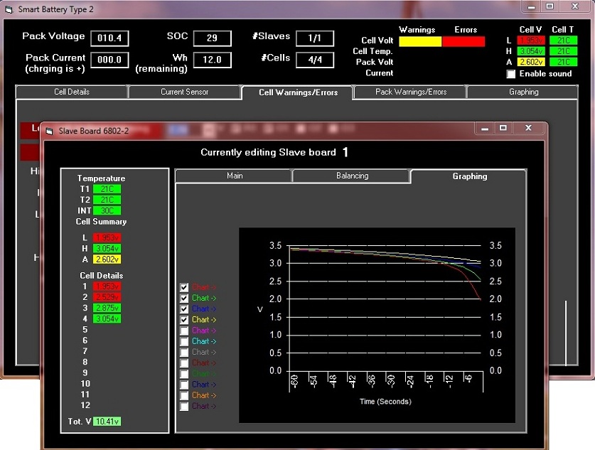 This
screen shows the final tab that has a graphing function to look at the
individual cell voltages. In this case, I have a 4 cell
E-Moli
pack and was discharging it at close to 10 amps (these are 2.9Ahr
cells) and you can see how quickly the cells go from a safe 3 volts
down past their lower 2.5 volt limit (less than 10 seconds)
You
will also note the number of alarms that are going off, highlighted by
yellow and red conditions (no cells were hurt during this
test!)
|
Zanthic Technologies Inc. |